
_RHEA Calibration
- Objective:
Follow this procedure if the device exhibits any issues with level balance between channels or requires a tube replacement.
-
- Preliminary Steps and Important Information:
All signal levels are in dB scale; please note that they must be converted to the dBFS scale of your specific audio interface. For instance, if the maximum output level of your audio interface is +18dB (0dBFS), then 0dB will correspond to -18dBFS.
Allow the device to warm up for a minimum of 30 minutes.
When replacing tubes, ensure you use a matched pair. If you encounter any issues setting the DRY/WET levels, please contact us by mail at support@wesaudio.com
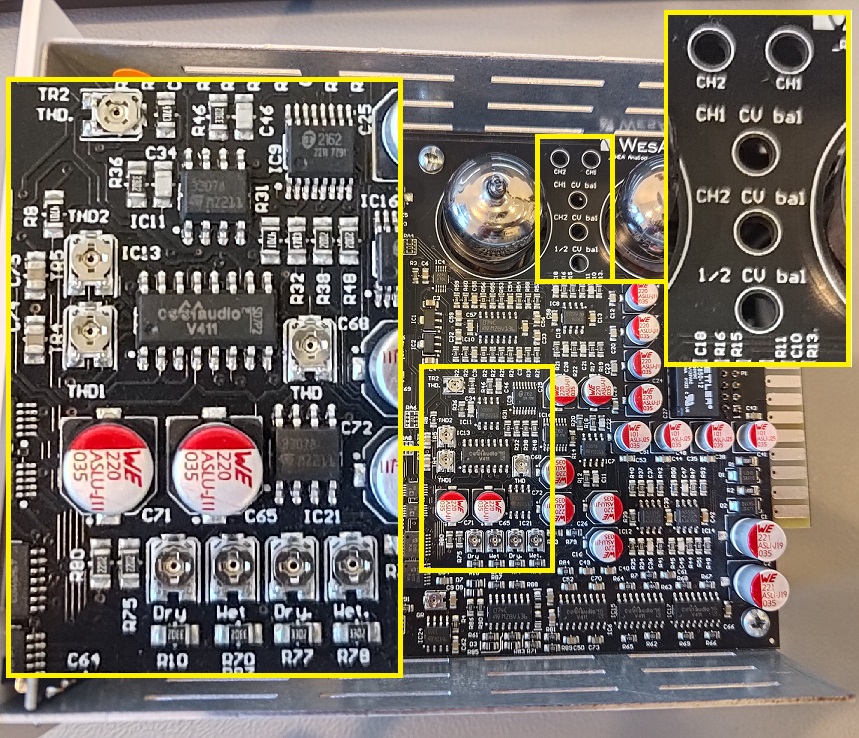
Trimmer locations (upper PCB):
- Tools needed:
- Small slotted screwdriver.
- 500 series extender for two slots (stereo).
- Software needed:
- GCon Software: Version 9.1.xxx or higher, available at: https://wesaudio.com/download/.
- Room EQ Wizard (REW): Install REW software for audio measurement, ensuring you select the option to run multiple instances during installation. This allows the use of both channels (Windows only). Download it from: https://www.roomeqwizard.com/.
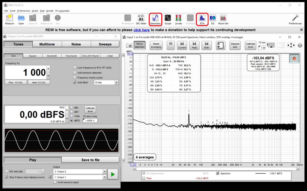
From the main REW window, open “Generator” and “RTA”, as shown in the picture below:
- Procedure:
- DRY Signal Level Adjustment:
_RHEA settings: INPUT 0, OUTPUT 0, MIX DRY (dry signal), THRESHOLD MAX, THD off, SC off
INPUT signal: sine wave @ 1KHz level 0dB
DRY Level: Adjust the DRY level to 0 dB for both channels using the trimmers labeled “DRY”
- WET Signal Level and THD Adjustment:
_RHEA settings: INPUT 0, OUTPUT 0, MIX WET (wet signal), THRESHOLD MAX, THD off, SC off
INPUT signal: sine wave @ 1KHz level 0dB
- THD Adjustment:
Adjust THD for both channels (as low as possible, approximately 0.02%) using the trimmers labeled “THD”
- WET Level Adjustment:
Adjust the WET level to 0 dB for both channels using the trimmers labeled “WET”
- THD MED and HIGH Adjustment:
(Optional, as MED and HIGH settings typically remain unchanged)
- Turn THD on and set to MED. Adjust “THD1” to achieve 1% (+1 dB signal level).
- Switch THD to HIGH and adjust “THD2” to achieve 2.5% (+3 dB signal level).
- Turn off THD after adjustments.
- Tubes Cathode Balance:
_RHEA Settings: INPUT 0, OUTPUT 0, MIX WET (wet signal), THRESHOLD MAX, THD off, SC off
INPUT Signal: sine wave @ 1KHz level -40dB
Adjust THD for both channels to as low as possible (1% or less) using the trimmers labeled “CH1” and “CH2”.
- CV Balance:
_RHEA Settings: INPUT 0, OUTPUT 0, MIX WET (wet signal), THRESHOLD MIN, ATTACK 1mS, RELEASE 0.3S, THD off, SC off
INPUT Signal: sine wave @ 1KHz level +10dB
Adjust THD for both channels to as low as possible using the trimmers labeled “CH1 CV bal” and “CH2 CV bal”.
- Between Channels CV Balance:
INPUT Signal: sine wave @ 1KHz level 0dB
Adjust the signal balance between channels (ensure equal levels on both channels) using the trimmer labeled “½ CV bal”.
-
- Final Check:
Repeat all steps from the Procedure section to ensure the device is properly calibrated. If any differences greater than 0.2 dB are observed, repeat the adjustment at the corresponding step where it is required.
If you need any immediate assistance, please contact us by mail at support@wesaudio.com
_RHEA VU Calibration
-
- Objective:
Follow this procedure if your device’s hardware (HW) gain reduction (GR) meter displays different values than the plugin GR meter.
-
- Preliminary Steps and Important Information:
Check if the HW GR meter is correctly set to the “0” position. Refer to the detailed procedure below for guidance.
Meter calibration settings: INPUT 0, OUTPUT 0, THRESHOLD MAX, MIX WET, ATTACK 1mS, RELEASE 0.3S, THD off, SC FILTER off.
Instructions on how to open GConManager in admin mode can be found here: https://wesaudio.com/faq/.
For certain units, the maximum compression level may be less than 20 dB.
Allow the device to warm up for at least 30 minutes before proceeding.
-
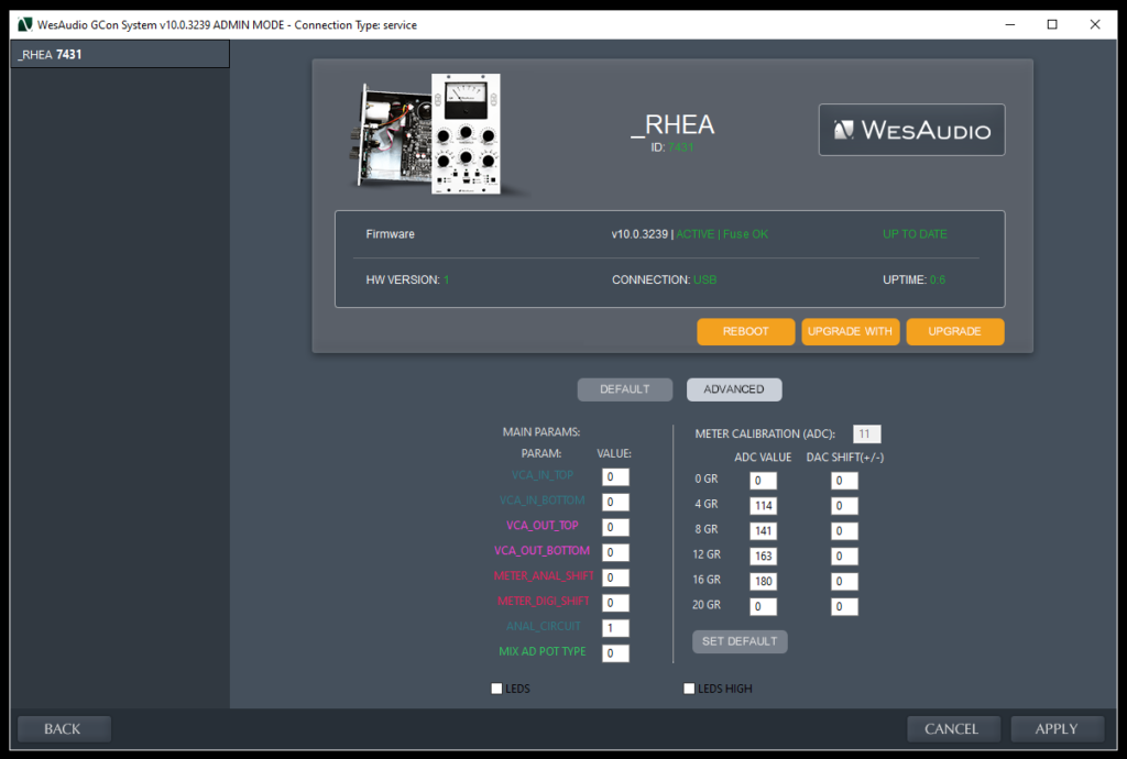
- GConManager Fields Description:
The grayed-out field “METER CALIBRATION (ADC)” displays the measured ADC value, which serves as a reference point for calibrating each compression level. This acts as a software reference for matching compression levels.
- “ADC VALUE” Column:
- Used to set both meters.
- Values must remain within the 0–255 range.
- For 0 dB, do not input a value lower than 16 (with 0 calibrated as 20).
- “DAC SHIFT (+/-)” Column:
- Provides compensation for the physical meter.
- Values must remain within the ±99 range.
- Use positive or negative values based on the needle position:
- If the physical needle needs to move left to display a specific compression level, use a negative value.
- Adjust accordingly for precise alignment of the meter.
-
- Tools and Equipment Needed:
- A small slotted screwdriver may be required to adjust the “0” position on the HW GR meter.
- An audio interface is also necessary for the calibration process.
-
- Software Needed:
- GCon Software: Version 9.1.xxxx or higher is required (admin mode). The software can be downloaded from: https://wesaudio.com/download/.
- _RHEA Firmware: Ensure _RHEA is updated to at least v9.1.xxxx firmware.
- DAW Software: A digital audio workstation with a tone generator insert and level measurement functionality (e.g., via a plug-in) is required.
- Procedure:
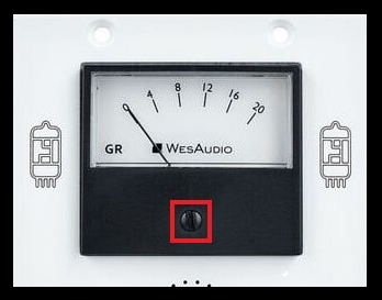
Before powering on the device and with the USB cable unplugged, check if the needle on the HW GR meter indicates “0”. If calibration is required, adjust it by turning the small black screw located just below the meter scale. Refer to the picture below for guidance.
When the device has warmed up, follow these steps:
- Send a 1 kHz sine wave signal from the tone generator to the device and receive the signal back in your DAW.
- Apply the settings specified in step 2.
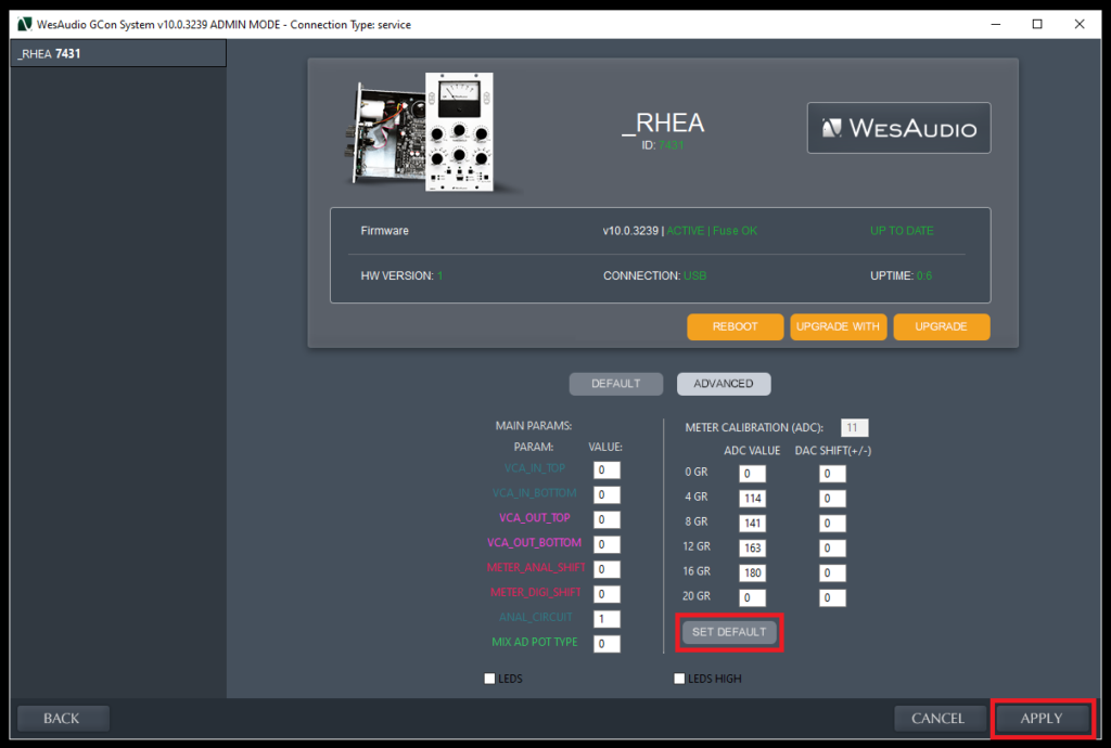
- Open GConManager in admin mode, navigate to the config section, and select your device from the list on the left side.
- In the “ADVANCED” tab:
- Press the “SET DEFAULT” button to set the default ADC values.
- Click the “APPLY” button to save the changes.
Refer to the picture below for additional guidance.
- Plug-in GR meter calibration:
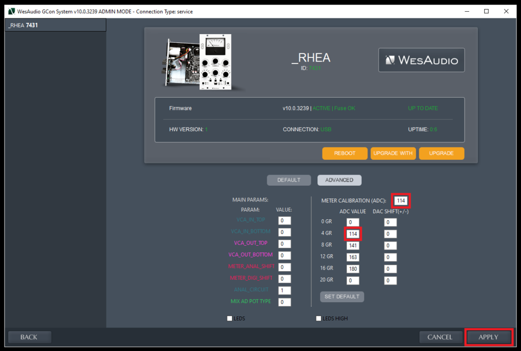
- 4dB GR calibration:
- Adjust the THRESHOLD to achieve an output level that is 4 dB lower than the input level.
- Read the ADC value displayed in the “METER CALIBRATION (ADC)” field.
- Enter this value into the 4 dB ADC field.
- Press the “APPLY” button to save the changes.
This step is critical as it defines the range of values required for accurately setting 1 dB compression in the next stages.
- 8dB GR Calibration:
- Set the THRESHOLD to achieve an output level 8 dB lower than the input level.
- Read the ADC value from the “METER CALIBRATION (ADC)” field.
- Enter the value into the 8 dB ADC field.
- Press APPLY to save the settings.
- 12dB GR Calibration:
- Set the THRESHOLD to achieve an output level 12 dB lower than the input level.
- Read the ADC value from the “METER CALIBRATION (ADC)” field.
- Enter the value into the 12 dB ADC field.
- Press APPLY to save the settings.
- 16dB GR Calibration:
- Set the THRESHOLD to achieve an output level 16 dB lower than the input level.
- Read the ADC value from the “METER CALIBRATION (ADC)” field.
- Enter the value into the 16 dB ADC field.
- Press APPLY to save the settings.
- 20dB GR Calibration:
- Set the THRESHOLD to achieve an output level 20 dB lower than the input level.
- Read the ADC value from the “METER CALIBRATION (ADC)” field.
- Enter the value into the 20 dB ADC field.
- Press APPLY to save the settings.
Note:
If your unit’s maximum compression is less than 20 dB (e.g., 18 dB), enter a higher value than the reading to match the actual compression level.
- HW GR Meter Calibration:
-
- 4dB GR Calibration:
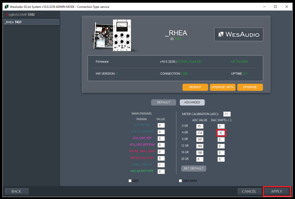
- Set the THRESHOLD to achieve an output level that is 4 dB lower than the input level.
- Match the HW GR meter with the plug-in GR meter by entering the appropriate value into the 4 dB “DAC SHIFT (+/-)” field.
- Press APPLY to save the adjustment.
- 8dB GR Calibration:
- Set the THRESHOLD to achieve an output level 8 dB lower than the input level.
- Match the HW GR meter with the plug-in GR meter by entering the appropriate value into the 8 dB “DAC SHIFT (+/-)” field.
- Press APPLY to save the adjustment.
- 12dB GR Calibration:
- Set the THRESHOLD to achieve an output level 12 dB lower than the input level.
- Match the HW GR meter with the plug-in GR meter by entering the appropriate value into the 12 dB “DAC SHIFT (+/-)” field.
- Press APPLY to save the adjustment.
- 16dB GR Calibration:
- Set the THRESHOLD to achieve an output level 16 dB lower than the input level.
- Match the HW GR meter with the plug-in GR meter by entering the appropriate value into the 16 dB “DAC SHIFT (+/-)” field.
- Press APPLY to save the adjustment.
- 20dB GR Calibration:
- Set the THRESHOLD to achieve an output level 20 dB lower than the input level.
- Match the HW GR meter with the plug-in GR meter by entering the appropriate value into the 20 dB “DAC SHIFT (+/-)” field.
- Press APPLY to save the adjustment.
- 1dB GR Calibration:
- Set the THRESHOLD to achieve an output level 1 dB lower than the input level.
- Match the HW GR meter with the plug-in GR meter by entering the appropriate value into the 0 dB “DAC SHIFT (+/-)” field.
- Press APPLY to save the adjustment.
- Final check:
Review each compression level (0–20 dB) to ensure accuracy. Adjust the corresponding values if necessary to achieve proper calibration.