Sidechain Feedback Adapter – Connection
Unlock New Dimensions of Control: Expand Your ngBusComp with Feed Backward Compression for Smoother, Classic Tones!
In a feed-forward compressor like the ngBusComp, the control signal is derived before the audio reaches the compression circuit, resulting in more precise control. However, with the ‘Feedback Insert Module’, the compressed signal is fed back into the sidechain, allowing for a smoother, more musical response that emulates the classic characteristics of analog compression.
Important Note About the Feedback Adapter!
The Feedback Adapter for the ngBusComp is designed to function optimally in Dual and Stereo modes. Please note that it will not work as intended when the unit is operating in MS (Mid/Side) mode.
Reason for Incompatibility in MS Mode:
In MS mode, the EXT input is routed directly to the sidechain circuit and is expected to receive a signal in Mid/Side format. As a result of this routing, the signal from the compressor’s OUTPUT, configured in Left/Right mode, will not properly trigger the sidechain detector.
For best results, please use the Feedback Adapter in Dual or Stereo modes only.
This chapter describes the installation of the Sidechain Feedback Adapter, which allows the use of an external sidechain circuit to create a feedback compression mode.
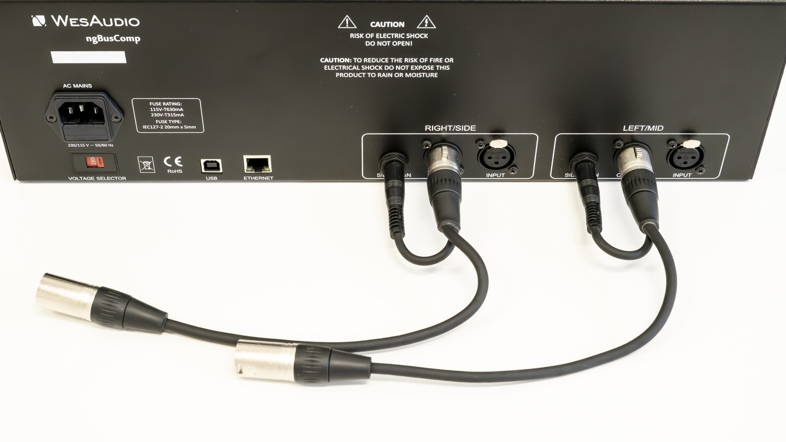
- Connect the jack plug to the Sidechain input.
- Plug the female XLR end of the cable into the Output socket.
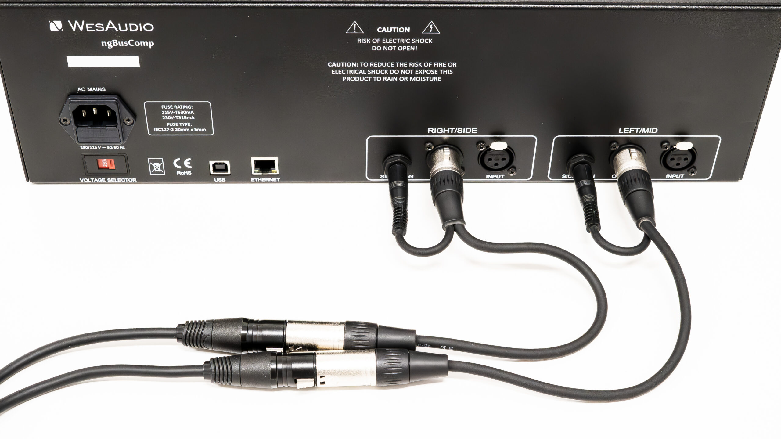
3. To properly connect your setup, plug XLR cables into the male XLR connectors that are already connected to another device. If you have Y cables of sufficient length, simply plug them into the device that you want to use in combination with the ngBusComp.
Sidechain Feedback Adapter – HOWTO Solder Your Own Y Cable
In this guide, you will learn how to create your own custom cable for the ngBusComp‘s backward mode connection. Soldering your own cable is a valuable skill that will enable you to optimize the sidechain functionality and ensure the best performance for your audio setup.
This tutorial will walk you through the necessary steps and materials required to successfully build the cable for backward mode operation.
Essential Tools for Soldering Your Own Cable
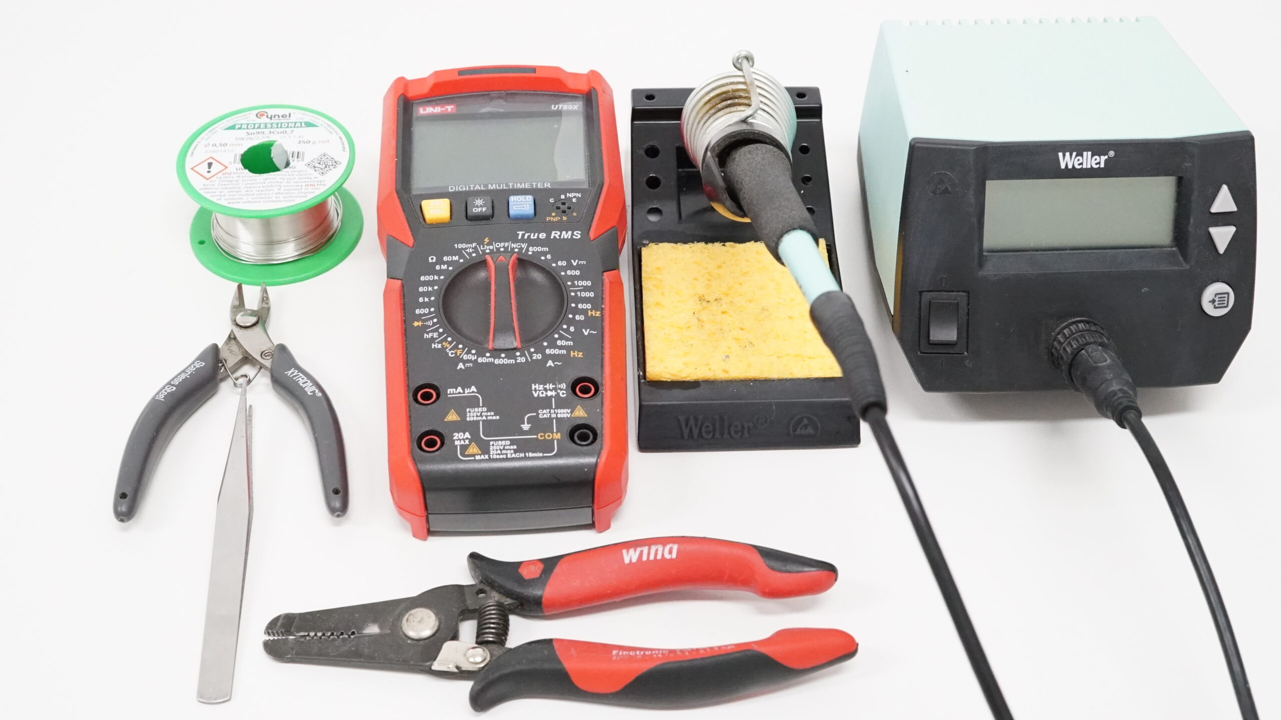
The tools you will use to make the cable are as follows:
- Soldering iron
- Solder
- Wire cutters
- Tweezers
- Wire stripper
- Multimeter (DMM)
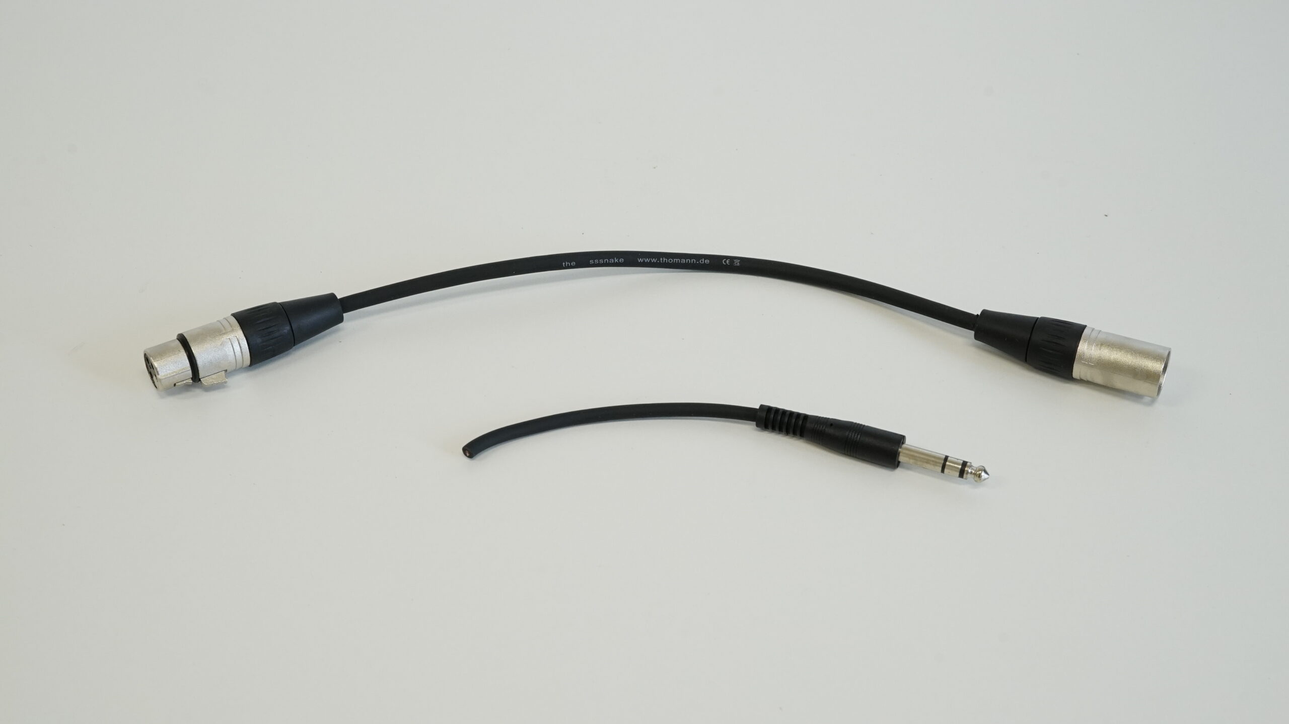
You will also need an XLR cable and either a TS (mono) or a TRS (stereo) jack cable.
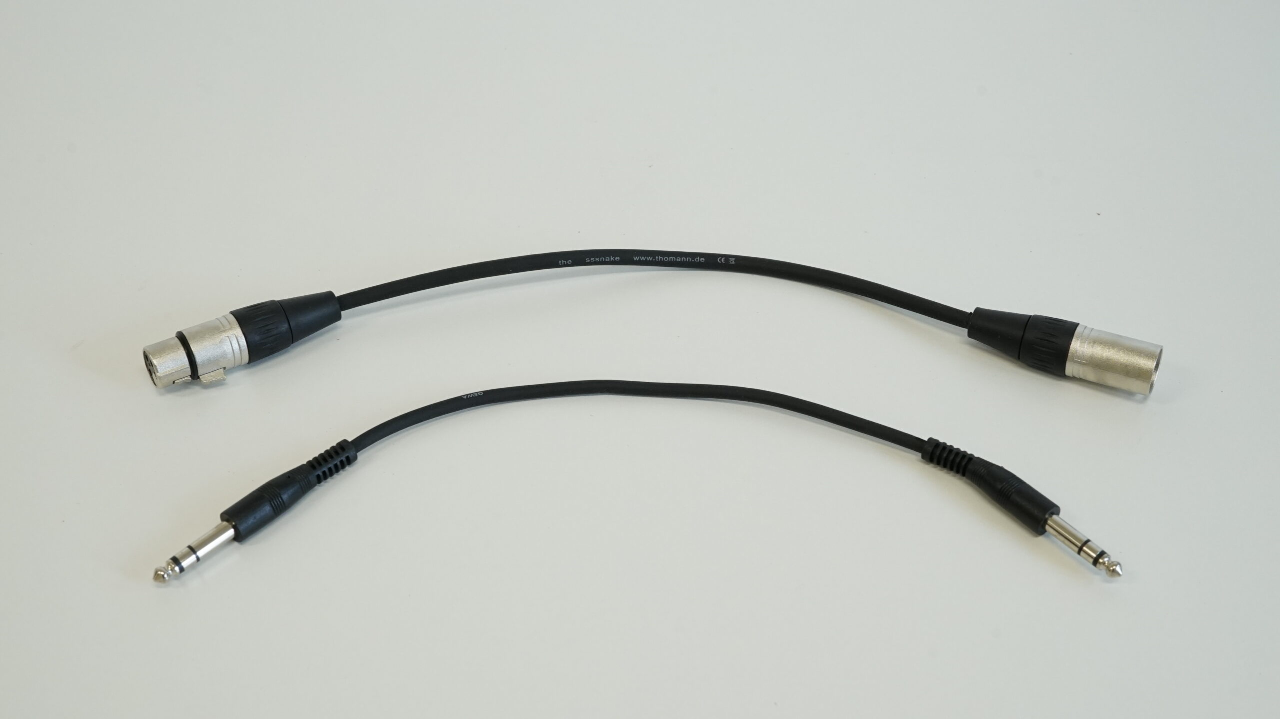
The first step is to cut the TS or TRS cable in half, as shown below.
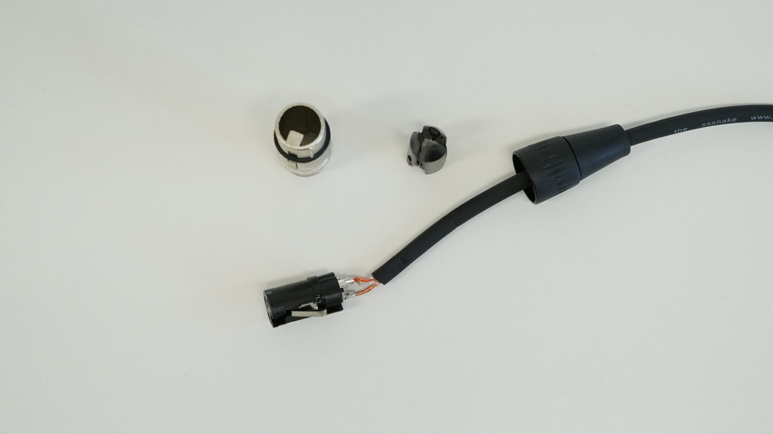
The next step is to unscrew the female connector and remove the plastic wire cover.
After disassembling the connector, you will need to remove the plastic piece located inside the strain relief (note that some cables may not have this component, so it’s worth checking the inside of the strain relief to be sure). To remove the plastic, use tweezers by inserting them through the side with the smaller opening in the strain relief and gently pushing the plastic out.
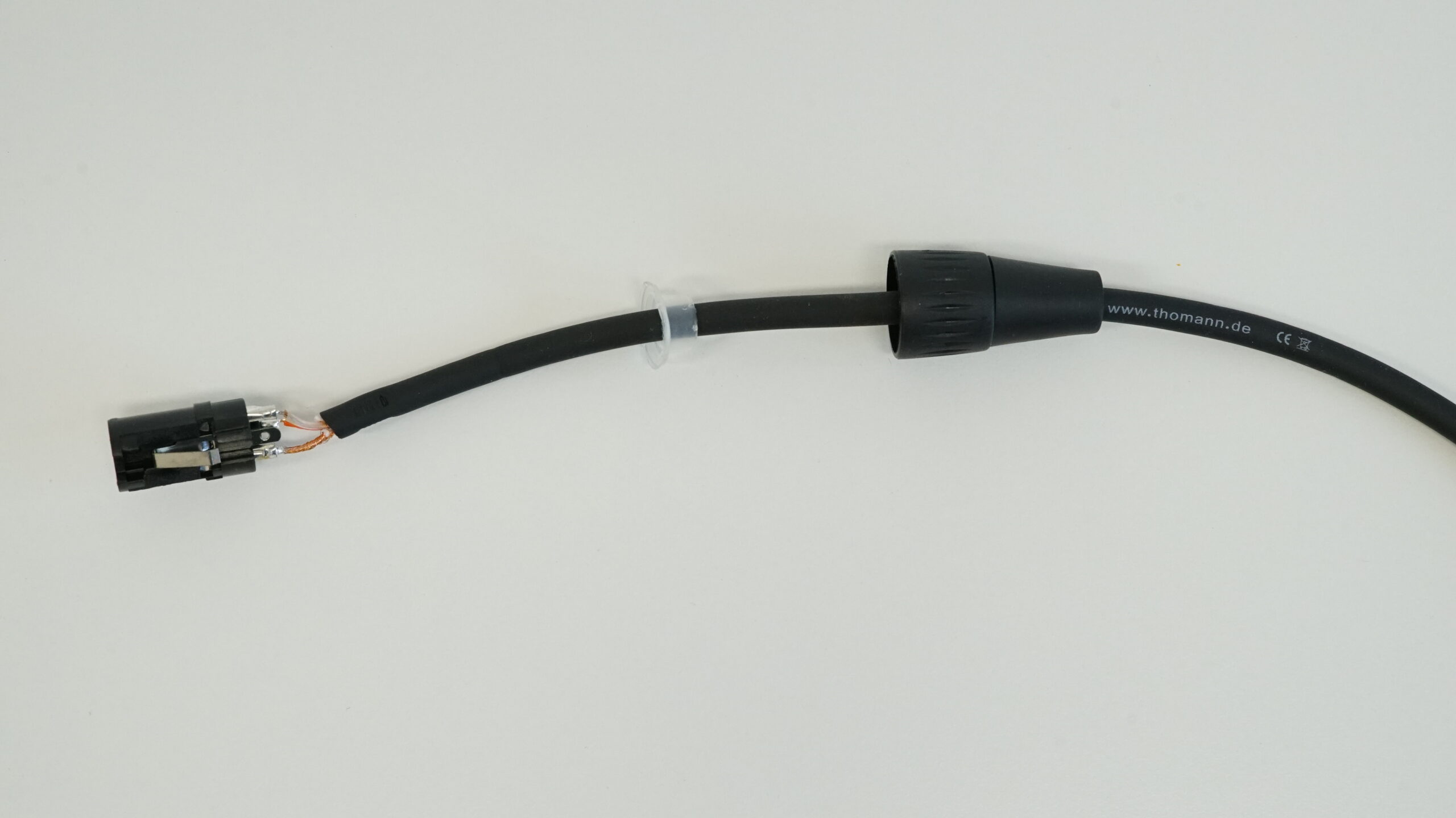
Once you’ve pushed the plastic element out of the strain relief, take wire cutters and cut the plastic piece off the cable. If you don’t remove this piece, you won’t be able to pass the jack cable through the strain relief in the later steps.
Preparing the Jack Cable for Soldering to the XLR Cable
Now, take the cut jack cable and strip about 1 cm of insulation. Twist the shielding (braided wire) so it doesn’t connect with any of the inner wires. For a TS cable, there is only the shielding and a single insulated wire (referred to as “hot”). In a TRS cable, you’ll find the shielding and two insulated wires (referred to as “hot” and “cold”). Strip the insulation from each wire, and it’s best to twist the shielding on each of them. Make sure not to connect any of the wires together!
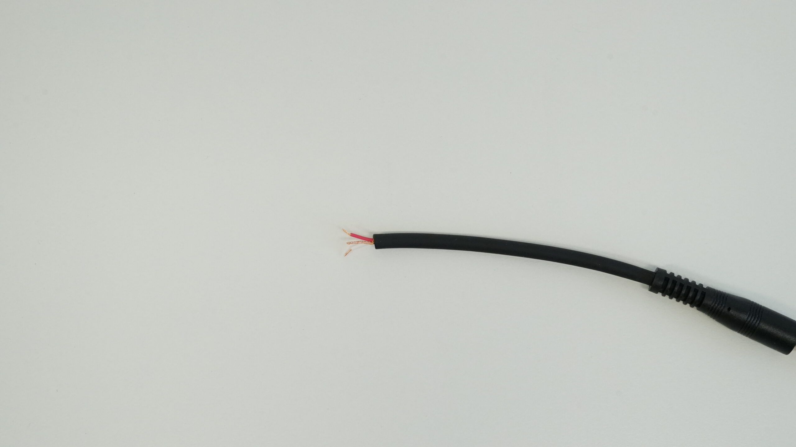
Take the multimeter, set it to the lowest resistance (ohms) range, and measure which part of the jack plug corresponds to which wire (or shielding).
To do this:
- Place one multimeter probe on the tip (hot)
- Place the other probe on the exposed section of the wire.
- When the multimeter shows a resistance value, it means the wire you’re measuring is connected to that specific part of the jack plug (where you’ve placed the other probe).
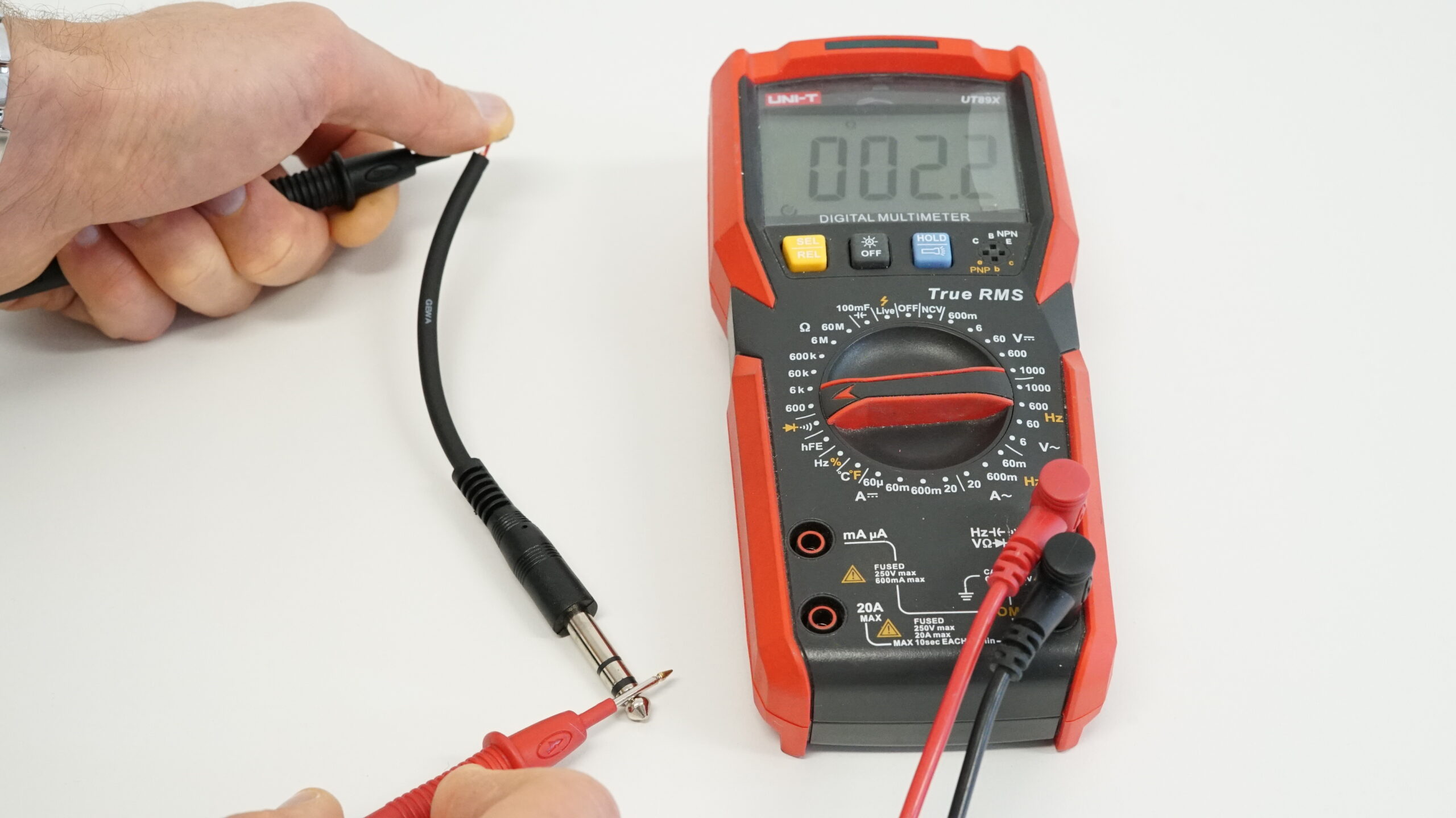
Once you’ve identified the tip (hot) wire, cut off the other two wires, leaving the tip (hot) wire intact!
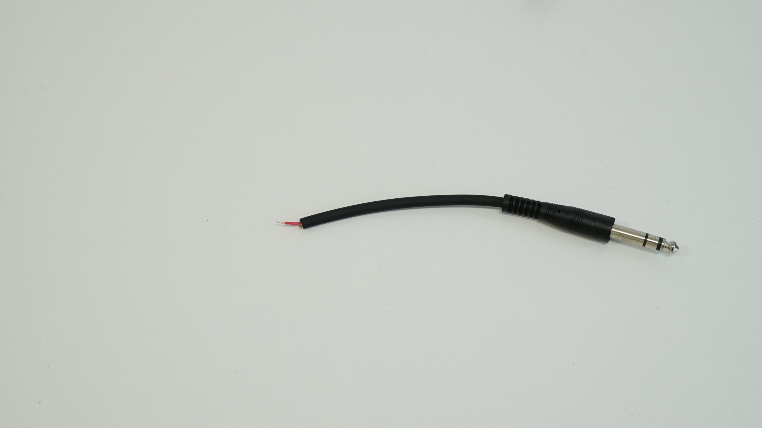
The stripped part of the wire needs to be tinned. To do this, turn on your soldering iron and prepare the solder. Allow the soldering iron to heat up for about two minutes to reach the right temperature (under no circumstances should you touch the shaft or tip of the soldering iron, as this can cause serious burns!).
Unroll a bit of solder, and then place the wire and the soldering iron tip onto the solder. The solder should melt and evenly coat the entire exposed part of the wire as you make a gentle back-and-forth motion.
The next step is to thread the jack cable through the strain relief. This is necessary because, without doing this, you won’t be able to assemble the XLR connector once you’ve soldered the jack cable.
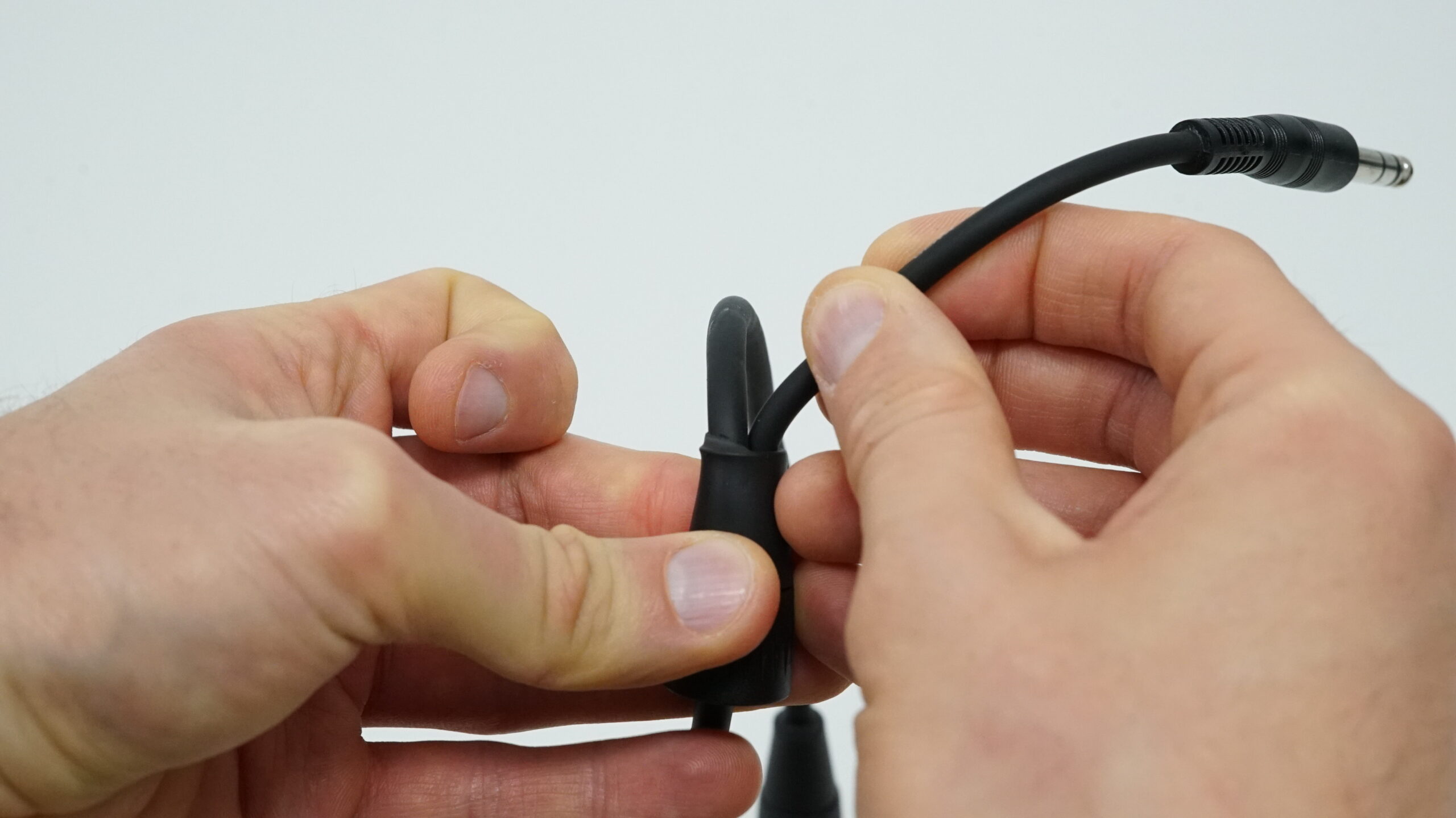
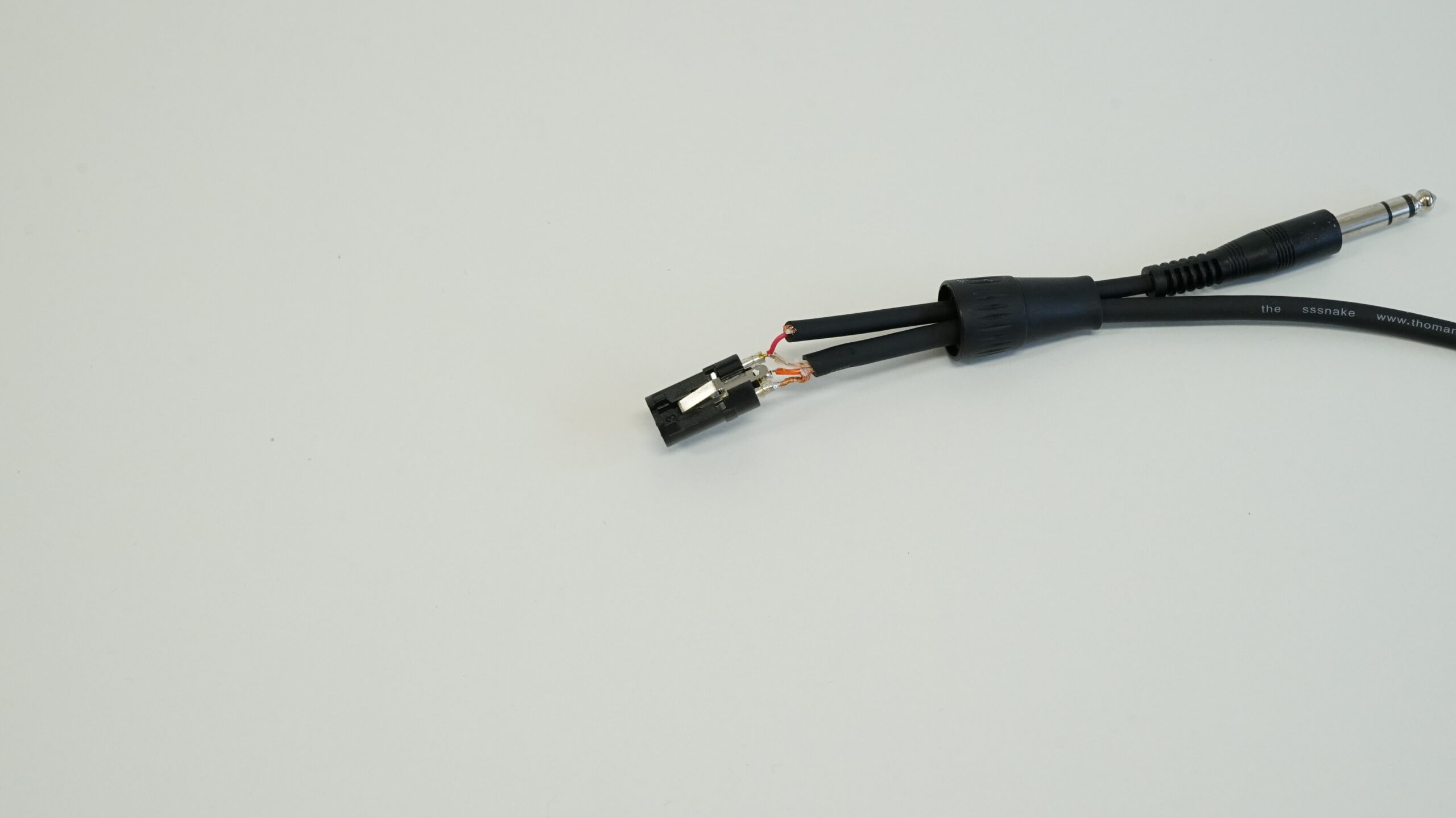
Before assembling the connector, it’s a good idea to test everything with a multimeter to ensure it’s done correctly. To do this, you should:
- Turn on the multimeter and set it to the lowest resistance (ohms) value.
- Insert one test lead into the hole marked 2 on the female XLR connector.
- Place the other test lead on the TIP (hot) of the jack cable.
If you see a resistance value on the multimeter, it means everything has been done correctly. If not, please go back to the previous steps to review and correct any potential mistakes.
All that’s left is to assemble the connector. The first thing you need to do is fit the plastic cover, which will shield and protect the exposed wires. Once it’s in place, it should look like this:
Assembling the XLR Connector
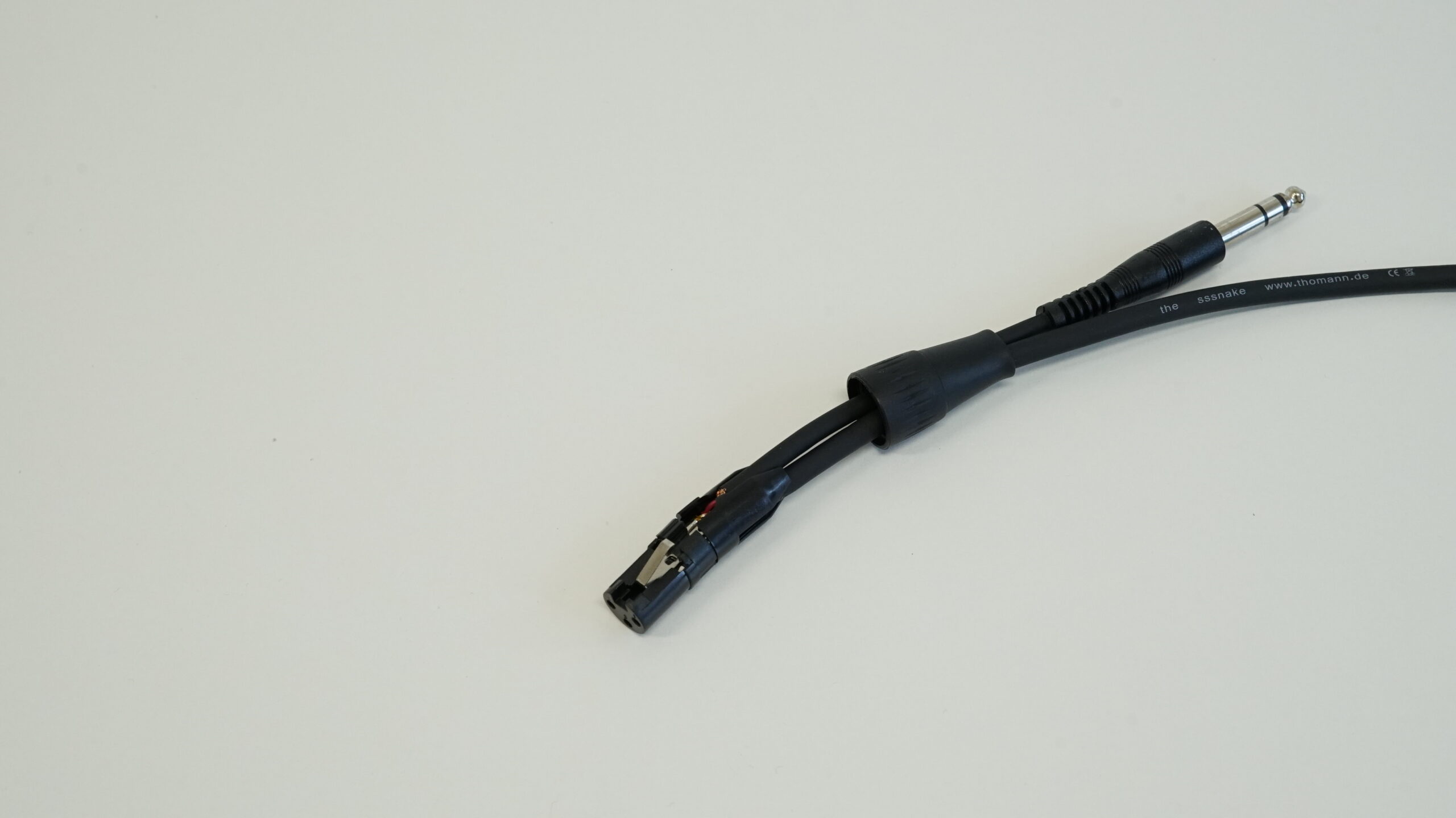
The final step is to fit the aluminum part onto the connector. The easiest way to do this is by turning the aluminum part upside down, then doing the same with the cable and sliding it into the piece. Once you’ve managed to do this, the next step is to secure it by tightening it together with the strain relief.
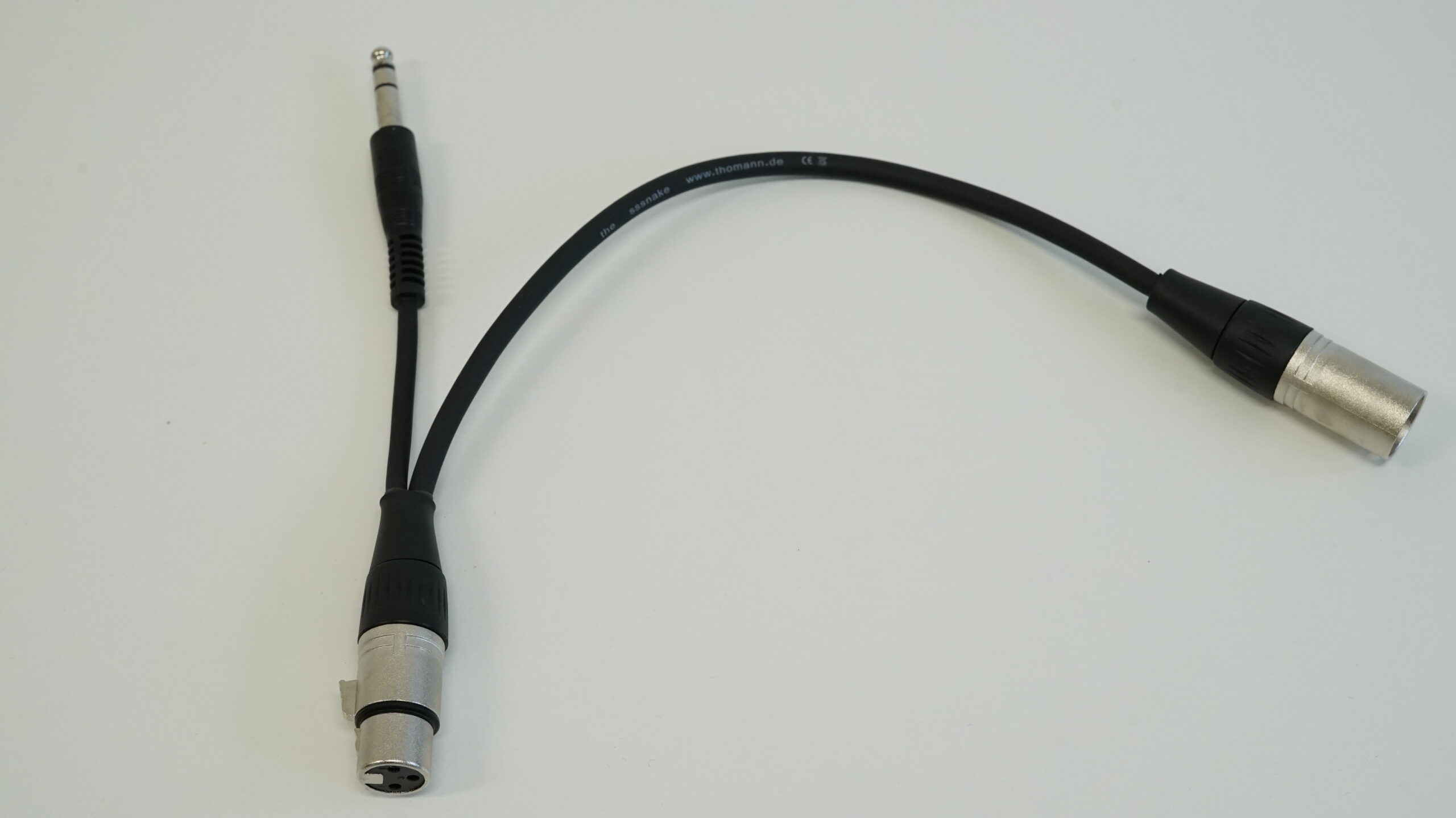
If you’ve completed all the steps outlined in this article, you now have a Y cable that you can use with your ngBusComp!
